Building an MMDVM based Quad Mode Digital and and SVXlink Analog Repeater using a Kenwood TKR-850
Due to the lack of Digital Mode repeaters around my home QTH, I had been running MMDVM hotspots built around Philips / Simoco PRM80s on 2mx and Philips FM92’s on 70cm for around a year, with G4KLX based DSTAR hotspots using soundcards or DV-RPTR boards for several years prior to that.
In early 2017 I decided to start acquiring the parts needed to build a full repeater stack that could operate initially as Digital repeater supporting D-Star and DMR in an effort to encourage some further digital activity and replace my low power hotspots with a full duplex repeater capable of providing service over a larger area.
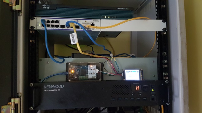
During March 2017, I purchased a Kenwood TKR-850 standalone UHF repeater that had been re-aligned for service on the 70cm Amateur band and I began the process of interfacing it with the MMDVM to provide the digital repeater functionality.
I now have a fully functioning repeater across all MMDVM Modes plus Analog functionality with Echolink running temporarily under my personal callsign while I apply for a repeater license:
TKR-850 Repeater Configuration
Channel Programming
In order to use the MMDVM or any other external repeater controller with the TKR-850, each repeater “channel” used for MMDVM must be programmed to operate in the “Duplex” operating mode rather than the standard “Repeat” mode used for standard Analog FM repeater operation.
Configuring the channel as “Duplex” operating mode disables the internal analog FM repeater function within the TKR-850 and allows the MMDVM to act as an external repeater controller, overlaying the multi-mode digital repeater functionality including periodic repeater identification via CW.
The following screenshot provides an example configuration for a TKR-850 based MMDVM repeater operating on 438.400Mhz (-5Mhz Input):-
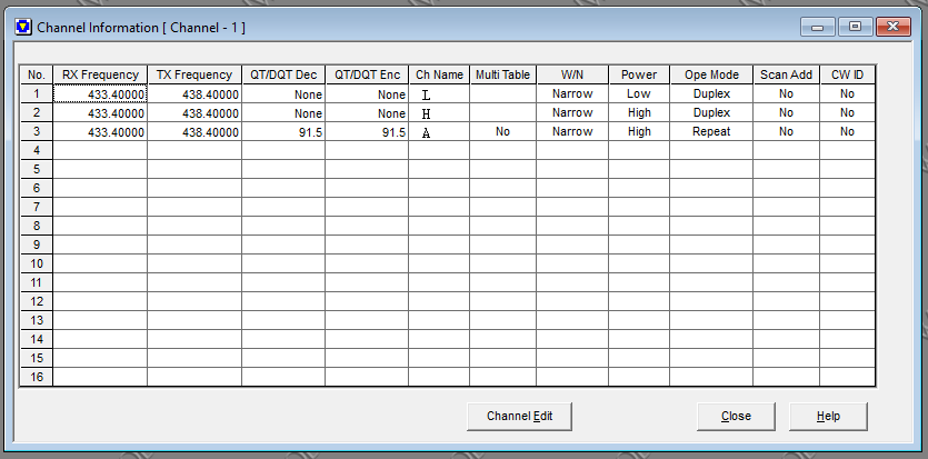
In this example the 3 channels are configured for the following purposes:-
- Channel 1 provides low power operation for testing or temporary demonstration use of the MMDVM repeater.
- Channel 2 is the normal operating channel for the MMDVM repeater, with transmit power set to high.
- Channel 3 is a backup standalone Analog FM repeater channel, with transmit power set to high and a CTCSS tone of 91.5hz used on both transmit and receive.
This working example configuration is available for download here as a starting point for your own configuration.
Note: You will require the Kenwood KPG-91D repeater programming software to open this file
Transmit Data and Receive Data Levels
Depending on the existing configuration of the repeater it may be necessary to adjust the TXD and RXD levels to ensure correct operation of the MMDVM, as these levels directly control the output receive signal levels to the MMDVM and the transmit deviation applied to signals from the MMDVM.
During build of 5 repeaters, we found that most of them required the levels to be increased close to maximum for best operation on ZUM 1.0 boards.
If you have attempted to adjust the MMDVM receive and transmit levels using the trim-pots on the MMDVM board but cannot get it working reliably or in a particular mode, you can adjust these levels by connecting to the repeater using the KPG-91D software and opening the “Test” mode found under the “Program” menu:-
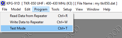
Once in test mode, you can select either TXD or RXD from the list of configurable items and adjust the slider as needed until it operates as expected.
Coming Soon: Screenshots of Test mode and how to adjust the levels
Interfacing the TKR-850 with the MMDVM
Generic Interface Guide
The TKR-850 conveniently provides all the basic required inputs and outputs via the DB25 Female Socket on the rear of the repeater, allowing easy connection to the MMDVM via a short interface cable using the following generic pin out applicable to all variants of the MMDVM boards (ZUM, SP8NTH etc):-
| MMDVM Pin | TKR-850 DB25 Pin |
|---|---|
| TX Audio | Pin 8 (TX Data Input) |
| TX Ground | Pin 19 (TX Ground) |
| RX Audio | Pin 10 (RX Data Output) |
| RX Ground | Pin 12 (RX Ground) |
| PTT | Pin 16 (External PTT Input) |
| COS | Unused |
ZUM MMDVM 1.0 Guide
| MMDVM Pin | TKR-850 DB25 Pin |
|---|---|
| Pin 1 - COS | Unused |
| Pin 2 - RX Audio | Pin 10 (RX Data Output) |
| Pin 3 - RX Ground | Pin 12 (RX Ground) |
| Pin 4 - TX Ground | Pin 19 (TX Ground) |
| Pin 5 - TX Audio | Pin 8 (TX Data Input) |
| Pin 6 - PTT | Pin 16 (External PTT Input) |
MMDVMHost Configuration
The main items to be aware of is that the TKR-850 requires TX and RX signal inversion with the MMDVM, along with a DMR Delay value of 7.
Example MMDVMHost Configuration
SVXLink Configuration
The open source application SVXLink is used to provide optional analog FM repeater and Echolink functionality alongside MMDVM, allowing the repeater to not only service all MMDVM supported Digital Modes but also regular FM analog users including the ability to operate as an EchoLink node if desired.
SVXLink is configured to expect a nominated CTCSS tone to be present on all FM Voice traffic, this is done to allow SVXLink to determine what is FM Voice that it should handle vs Digital traffic that should be ignored and handled by the MMDVM.
In addition SVXLink is configured to encode all FM Voice transmitted by the repeater with the same CTCSS tone, this provides FM Voice users with the ability to configure tone squelch on their radios so that they only hear analog traffic and their radio doesn’t open squelch when receiving digital output from the repeater.
The last important point is providing a method for the MMDVM to indicate to SVXLink that the repeater is busy in digital mode or for SVXLink to indicate to the MMDVM that the repeater is busy in analog mode.
An analog busy lockout signal can be provided by parallel wiring the PTT signal from SVXLink to the COS Pin of the MMDVM, with the pin being driven high indicating to the MMDVM that the repeater is busy on the analog side and that the digital half should be locked out.
Note: This requires the MMDVM firmware to be configured with #define USE_COS_AS_LOCKOUT in Config.h
Similarly a digital lockout signal can be provided using the mode indication pins on the MMDVM tied to a input GPIO on the raspberry pi or something else suitable, with SVXLink configured to interpret the pin being driven high as the repeater being busy on the digital side and that the analog half should be locked out.
Note: This requires the MMDVM firmware to be configured with #define ARDUINO_MODE_PINS in Config.h
PTT and Lockout Circuit Diagram
Coming Soon!
Example SVXLink Configuration
Coming Soon!
Things left to do
- Calibrate the RSSI levels and generate an RSSI .dat file for use with MMDVM